
In recent decades, the demands for designing smarter and safer vehicles has caused a significant increase in the size and complexity of the automotive systems software. In a modern high-end passenger car, more than 100 million software lines of code (SLoC) are embedded and distributed across as many as 80 ECUs communicating in a network infrastructure. In terms of SLoC, automobile code size is second only to Google’s internet services (2billions SLoC). This makes the modern passenger car one of the most complex systems being developed today. To effectively address this complexity while improving the efficiency and quality of automotive software, OEMs (Original Equipment Manufacturer) and suppliers formed a consortium back in 2003 to create AUTOSAR (AUTOmotive Open Software Architecture) as an integrated standard for vehicle software development. The first AUTOSAR architecture version was released in 2006. It’s now called AUTOSAR Classic and in 2017 another AUTOSAR standard (Adaptive) was created to address connected vehicles and autonomous driving applications.
In this article, we’ll explain how AUTOSAR Classic helps to deal with software complexity and introduce the main AUTOSAR concepts and terminologies the function developer should know.
Introduction to AUTOSAR Architecture Classic
Automotive systems are often developed in a collaborative effort between OEMs and suppliers. Suppliers develop subsystems specified by the OEM or develop their own subsystem that they sell as an “off-the-shelf” product. Before AUTOSAR, the collaboration relied on specification languages defined within the OEM-Supplier partnership. A new partnership began with an agreement on a new specification language, and integrating a proprietary supplier component required adaptation efforts. With the growing demand of new vehicle functions and the expansion into several domains, the old collaboration approach became impractical. Distributed functionalities in the vehicle architecture also added complexity. AUTOSAR architecture was created to make this complexity manageable, by providing a system-based design environment for the development teams creating the software architecture.
Modular architecture and virtual communication bus
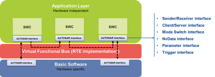
To manage the complexity, AUTOSAR introduced a modular architecture with layers to separate hardware-independent application software from hardware-oriented software.
- The upper layer, Application Software (ASW) hosts the application functions as individual software components (SWC).
- The lower layer, the Basic Software (BSW) includes low level software like services and hardware specific software.
- Between these layers is an abstraction layer called the Runtime Environment (RTE) that manages the interface between the two other layers.
The AUTOSAR architecture also provides a way to decouple the applications from the hardware infrastructure. AUTOSAR introduced the concept of Virtual Functional Bus (VFB) which makes it possible for the SWCs to interact independently from where they are executed in the system (inside one ECU or on different ECUs). As SWCs are allocated to the various ECUs, the virtual connections are mapped to local connections (intra-ECU) or onto network communication technologies such as CAN or FlexRay (inter-ECUs). The connection mapping is implemented by the RTE and becomes the concrete interface between individual SWCs and also between SWCs and the BSW (the RTE implements the VFB on a specific ECU).
With the VFB, OEMs and suppliers can develop multi-domains and competitive software without detailed knowledge on the lower-level technologies or dependencies. It gives the flexibility to scale the overall system afterwards (e.g. number of ECUs, ECU-to-Application mapping, network technology, etc.). It enables the reusability and transferability of software components and makes it easier to add new functions to the system. Moreover, the VFB validates all plausible communication between SWCs, which will detect any software architecture errors and improve the software architecture quality.
AUTOSAR Architecture - Application Software Layer
An AUTOSAR application consists of several software components interacting together.
Hierarchical architecture
The Application software layer offers a hierarchical structure to create the software components:
- Composition: Composition packages several SWCs to implement a subsystem. A composition has its own connections visible to the outside world. It’s possible to create a composition of compositions.
- Atomic software component: There are two kinds of Atomic software components: Application and Sensor-Actuator. Application software components implement (part of) an application. It can use all AUTOSAR communication mechanisms and services but it interacts with sensor or actuator hardware through a Sensor-Actuator software component. The latter has access to the ECU’s specific hardware I/O signals. “Atomic” means it cannot be further decomposed into smaller components.
AUTOSAR Interfaces
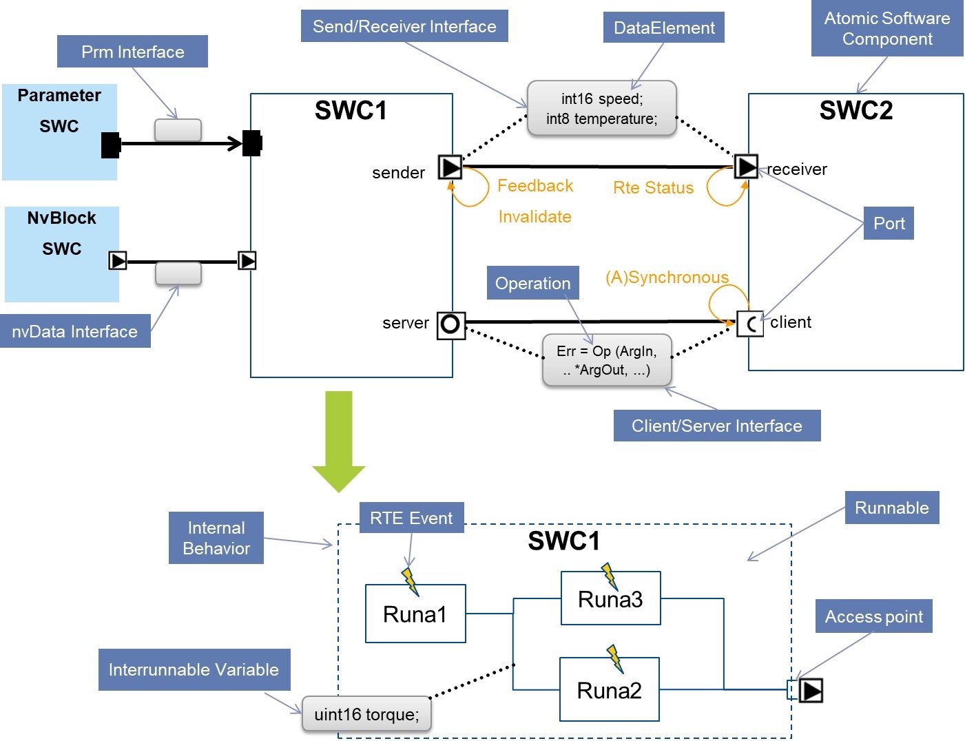
Software components communicate via “Ports”. A Port is a gateway that is used to request or send information. The semantics of the information depends on the kind of data or service being exchanged. A port must first be associated with an Interface which will define the exchanged information (e.g. request/send some specific data). One Interface can be referenced in multiple places, ensuring consistent data definitions for the provided port(s) and the related required port(s). The AUTOSAR Interfaces are:
- Sender/Receiver interface: Defines a set of data elements that are sent from one component to one or more components. The data-element is like a global variable which exchanges values. Sender/Receiver ports can be characterized with additional communication attributes like:
- RTE Status: returns an error code (e.g. timeout) or no error indicating whether or not the communication operation was complete.
- Signal Invalidate: a sender can decide to invalidate the signal and an invalid value is sent instead of the signal’s original value.
- Acknowledgment (Feedback): A sender can request an acknowledgment of the sender operation (i.e. data writing confirmation). The feedback signal returns an error after an acknowledgment timeout has expired.
- Client/Server interface: Defines a set of operations that a server-component can implement and one or several client-components can use or invoke. This mechanism is similar to a function call. The function can get, process and return data through function arguments.
- Parameter interface: Defines a set of parameter elements (constant or calibratable) that a “Parameter software component” (a specific type of component) provides to other components. Note: Parameters can also be defined within the scope of a SWC as part of the Internal Behavior (See below).
- Non-Volatile Data Interface: Provides read and write accesses to Non-volatile (Nv) data-elements. The Nv data elements are exchanged between an “Nv Block software component” (a specific type of component) and other software components. The Nv Block software component is responsible to handle the communication with the BSW modules accessing the physical non-volatile memory.
- Trigger Interface: Enables a SWC to trigger another SWC with the purpose of fast response time for triggers which might occur sporadically or at a variable cycle time. This could be useful for cases such as triggering a SWC based on the crankshaft and camshaft position to control ignition system and fuel injection.
- Mode-Switch Interface: Declares groups of modes that represent operating states of an ECU or a SWC. Modes are similar to enumeration values. A component providing modes is called a Mode Manager and the user component is called a Model User. The Mode Manager notifies the mode user when the mode has changed (switched). The Mode User can use the mode signal for an internal process (e.g. to disable or trigger an execution).
AUTOSAR Architecture – layers and interfaces
In the RTE, the respective communication interfaces are implemented with specific constructs called RTE API. E.g. Rte_Read_xxxx(), Rte_Write_ xxxx (), Rte_Call_ xxxx (), Rte_Invalidate_xxxx(), etc.
We’ve seen the communication mechanisms between SWCs. Now let’s look at how a SWC is implemented.
Internal Behavior of an Atomic software component
AUTOSAR Internal Behavior (IB) defines the architecture elements that implement the SWC. It describes the implementation from a code perspective. In the system design timeline, the IB can be specified only when the SWC needs to be implemented, while the structure of the SWC (e.g. the ports) need to be specified upfront. The IB also specifies if the SWC supports multiple instantiations, meaning the SWC is implemented once and instantiated several times in the ECU(s). This is comparable to the principle of a reusable function (e.g. Seat heating SWC instantiated on each seat). The main IB elements are:
- Runnables: These are the smallest pieces of code (basically C-functions) which implement the SWC functionality. A SWC can have one or multiple runnables. When the SWC supports multiple-instantiation, the runnable handles instance-specific data (e.g. the state variables) via an additional function argument.
- RTE-Event: The RTE-Event offers a mechanism to specify when to execute a runnable. For each runnable, an RTE Event defines whether the runnable needs to be called periodically or event-based (e.g. events related to communications like when a mode switches, when an operation is invoked, when a trigger signal is received, etc.).
- Access points: To access the information conveyed via the SWC ports, the IB defines access points between runnable and SWC ports. The access points specify how the runnable expects to access a data (buffered or not) or an operation (synchronous or asynchronous).
- InterRunnableVariable: Allows runnables within the same SWC to exchange data. It’s like an access to a global that is defined in the scope of the SWC. Runnables of different SWCs have to communication via the SWC ports.
- PerInstanceMemory: SWC can have states that need to be maintained during the execution. When the SWC is single-instance, a global variable is adequate, but for multiple instances, the states have to be stored in separate memory regions to avoid concurrencies between the instances. Hence, the state can be defined as PerInstaceMemory.
- Private calibration parameters: SWC can have parameters defined internally. The parameter can be defined per instance of the SWC (PerInstanceParameter) or can be shared between all instance of a software component (SharedParameter). Those are not accessible to other SWCs.
AUTOSAR Architecture – elements and terminology
AUTOSAR Architecture - Methodology and Templates
In addition to the architecture description, AUTOSAR provides a methodology that describes the process steps from the abstract system definition right down to the final EUC executable with a list of design steps and work products. It also provides templates (meta-model) to define design semantics and constraints called the “AUTOSAR Schema,” from which architecture description files can be created and exchanged (as AUTOSAR XML files). This encompassing approach allows all stakeholders of the system development to understand and speak the same language, which dramatically improves the collaborative development environment.Moreover, with the architecture being described in a machine-readable format, it can be processed by design tools to generate the necessary system components (e.g. RTE API calls in the SWC implementation, RTE implementation, BSW implementation including the Operating System, etc.)
Conclusion
AUTOSAR architecture makes it possible to develop application software on an abstraction level, focusing on the interactions between the software components. It offers a modular architecture with a hierarchical structure and standardized interfaces connecting architecture layers and components. More than just a design tool for a single ECU, AUTOSAR addresses challenges bringing together an entire system of interconnected ECUs. It offers a wide range of communication and implementation techniques to develop complex automotive software applications. The standardized exchange formats, encourages collaborative development and enables the creation of software as off-the-self products which can be integrated into any AUTOSAR environment. The machine-readable description of the software architecture enables interoperability between design and test tools (e.g. model-based development tools like Simulink or TargetLink have the ability to read AUTOSAR files, making it possible to generate AUTOSAR compliant code and test it in a tool like BTC EmbeddedPfatform). Last but not least, for safety critical software development, many AUTOSAR mechanisms support the architecture design methods recommended in standard like ISO 26262.